
As we have stated, computers use the binary number system to perform computation. The two binary digits '0' and '1' can be represented by the voltage level on a wire. For example, no voltage (0 volts) could represent '0' where as +5 volts could represent '1'. We also have seen that the binary number system lends itself easily to representing Boolean algebra expressions, where '0' means FALSE and '1' means TRUE.
Just as the Boolean values have an electrical equivalent in a computer, so do the basic operations of conjunction (and), disjunction (or), and complementation (not). Each of these operations can be computed by a device called a logic gate.
You can think of a logic gate as a black box with wires going into it and out of it. Suppose we had a logic gate to compute and. The and operation has two inputs and one output. For example, the Boolean expression AB has the two inputs A and B and a single output, which is their conjunction. The corresponding logic gate for and will have two input wires, one carrying a voltage which represents the current value of A, and another carrying a voltage which represents the current value of B. This gate would have one output wire, and (based on the values of the input wires) would output the result of the operation on it.
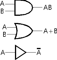
Since we will be different kinds of gates to make larger, complex circuits, we need an easy way to easily identify the function of a gate which appears on a circuit diagram. We use different shapes to represent the types of gates. The figure below shows the three basic logic gates and the corresponding Boolean operations they perform. These are the basic building blocks of all digital logic circuits.

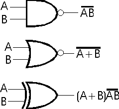
There are also special gates for nand, nor, and xor.

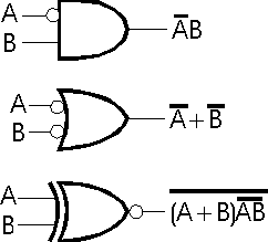
You'll note the use of the inversion bubble in the drawing of nand and nor. The inversion bubble can be used to complement a value going into or coming out of a gate. Here are some examples of inversion bubble use:

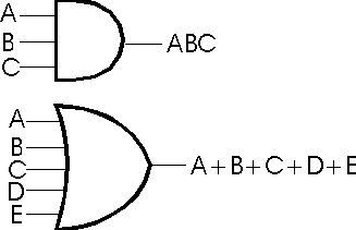
Sometimes we need gates which have more than just two inputs. In such cases, we draw them as follows:

Previous Module: Logic, Truth Tables,
and Boolean Algebra
Next Section:
Logic Circuits and Boolean Algebra
Return to
Module Index