For the sake of time, we won't cover Karnaugh maps. That means to omit appendix 3A in 4th ed, or Section 3.4 in the 5th. It's an interesting topic which you might enjoy, but you won't be responsible for it on exams.
You are not responsible for the material in Sec. 3.6.6 (4th) ed., or 3.7.6 (5th).
- Boolean.
- Boolean operators.
and: both true none, ⋅, ∧ or: either true +, ∨ not: invert overbar, ¬, trailing ′ nand: not and nor: not or xor: different ⊕ - Boolean Expressions.
- Truth Tables
- Boolean Algebra Laws
- Boolean Algebra Examples.
- Cannonical Forms.
- Sum-of-products. The OR of conjuncts of the input variables, or inverted input variables.
- Product-of-sums. The AND of disjuncts of the input variables, or inverted input variables.
- A systematic way to build an expression from a truth table.
- Example
- Boolean operators.
- Digital Circuits.
- Gates: Electronic circuits which compute the boolean functions.
- Building gates from transistors.
- Versions with more than two inputs available.
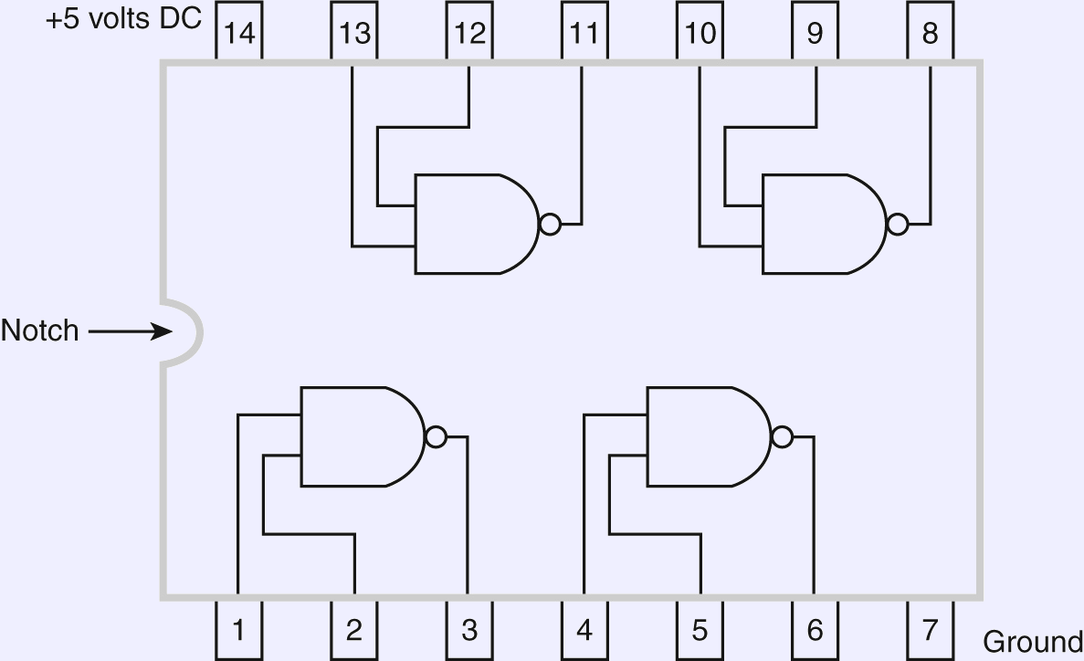
- Manufactured in groups on a chip.

not
and
or
nand
nor
xor - Combine the devices to build more complex circuits.
- Useful Combinational Circuits.
- Combinational circuits are also functional: Produce an output which is a function of the current inputs.
- Adders
- One-bit adder: One column of a binary add.
- Inputs: Each data bit and a carry in.
- Outputs: The sum bit and the carry out.
- Carry propagation adder: Combine for needed bits.
- Connect each carry-out to the next carry-in.
- Send 0 as carry-in to the rightmost bit.
- Two banks of input signals for the arguments, one bank for the result.
- Carry-out of the high bit is the carry-out of the addition.
- One-bit adder: One column of a binary add.
- Subtraction.
- Build a subtract unit using twos compliment and addition. a−b=a+(−b).
- Negate the second input so that adding it to the first accomplishes a subtract.
- Recall: We negate a value by inverting each bit, then adding 1.
- Start with the same adder.
- Invert each bit of the second input with a bank of not gates.
- Change the carry-in to the low bit to one. This adds the one by adding it to the sum.
- Decoder
- A binary number selects which output on which to send the value 1 (others get zero).
- Demo
- Implementation
- Multiplexor
- A binary input selects which of several input signals to send to the output.
- Demo
- Implementation
- Arithmetic and Logic Unit (ALUs)
- An ALU is a circuit which can compute any of several functions as determined by an input function code.
- Very important in CPU design.
- Some clever ways to do this.
- Seven-Function ALU
- Combines two four-bit numbers to a four-bit result.
- Function Codes
- Eleven-function ALU
- Combines two eight-bit numbers to an eight-bit result. This is based on an example from Patterson and Hennessy.
- Function Codes
- Some techniques.
- Compute several things and use a multiplexor to select which one to output based on the function code.
- The bits of the operation code may be used individually as boolean flags.
- Use an and gate to conditionally block a signal.
- Use an xor gate to conditionally invert a signal.
- Use an adder to subtract by inverting all the B inputs and feeding a 1 to the initial carry-in.
- State Devices
- State devices have memory: They produce an output which depends on both the current and previous inputs.
- Book uses “sequential circuit,” which is descriptive, but does not seem to be very standard.
- Clock: Not a state device. Generates a square wave.

- Flip-flops. Change state based on clock signal.
- Level-triggered.
- Edge-triggered, leading or trailing.
- We'll usually use leading edge-triggered.
- Building them.
- Uses feed-back to maintain the state.
- Unclocked SR, Level-clocked SR
- Level-clocked D
- Register. Collection of D flip-flops.
- State machines.
- Finite State Machine (FSM): A theoretical construct.
- Deterministic Finite Automaton (DFA): Changes state on input.
- Moore Machine: Output value associated with each state, transitions on input.
- Mealy Machine: Transitions on input changes, outputs with transitions.
- Algorithmic State Machine (ASM): Sort of a flowchart.
- A real digital machine with state devices and a clock. The state changes when the clock ticks.
- An FSM may be used to model the behavior of a real machine.
- Counter.
- The increment unit is build with half-adders.
- The collection of D-flip-flops constitutes a register.
- Finite State Machine (FSM): A theoretical construct.
- Gates: Electronic circuits which compute the boolean functions.
Questions
I'm suggesting chapter questions listed below, with question number varying by edition. There seems to be some changes in the questions from 3rd to 4th, but 4th to 5th is generally just renumbering.
Chapter questions:
For chapter questions 49 and 50 (5th), 36 and 37 (4th), or 32 and 33 (3rd), find the boolean expression for the function computed, then simplify it if possible.
Try using the table in question 22 (4th or 5th) or 20 (3rd) to write a product-of-sums expression.
Use logisim to create a sequential circuit with four LEDs producing the following pattern:
You will need some flip-flops to hold the displayed bit values, and some logic to get them to change correctly when the clock strikes.