- Paging and Virtual Memory
- Paging is a technique for memory management.
- Requires significant hardware support.
- Eliminates the fragmentation problem.
- Most often used to implement virtual memory.
- User software sees more memory than is actually present.
- Often meaning memory seen by all running programs exceeds the installed memory, not that each program sees more.
- Part of the memory contents actually resides on disk, and is move to real RAM on demand.
- A forerunner: Overlays.
- An early (1960's) solution allowing a program to be larger than main memory.
- Programmer divides the program into a main part and one or more overlays.
- The main commands the O/S to move overlays into or out of memory.
- A lot of work.
- Which can suddenly be wasted when the boss buys a memory upgrade.
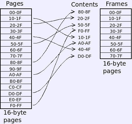
- Paging is a system of address translation.
- A program's address space is broken into equal-sized pages.
- The size of a page is some power of two.
- The physical memory is broken up into page frames (or real pages) of the same size.
- A program's pages are placed into pages in any order.
- Virtual addresses break into page number and offset.
- Translation replaces the page number with the correct frame number to produce the real address.
- For instance, if the program generates address A7, the page number (A)
is replaced with the frame number where the page is located (5) to
produce real address 5A. That address is sent to the main memory unit.
 Translation
0 1 2 3 4 5 6 7 8 9 A B C D E F 4 1 6 2 0 5 7 3
virtual = A7 → A 7 → 5 7 → 57 = real
- Page tables.
- In-memory table similar to the translation listing above.
- Each item in the page table describes one page, and is known, shockingly, as a page table entry (PTE).
- Array indexed by the virtual page number.
- Contains a bit to say if the page is in memory, the location in memory,
and other information.
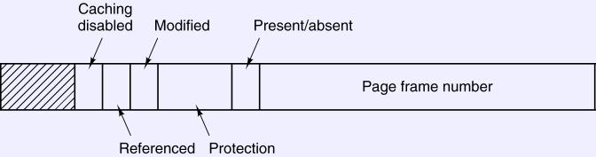
- The present/absent bit indicates that the page is present in real memory.
- The permission bits indicate what may be done with the page, typically read, write or execute (instruction fetch).
- The referenced and modified bits record when the page in memory is used or modified. More on these later.
- When a virtual address is generated:
- Hardware divides into a page number and offset parts, and uses the page number as offset into the page table.
- This locates the PTE for the virtual page.
- Make sure the permission bits are satisfied by the operation, or generate a fault.
- If the present bit is false, generate a page fault (OS takes over).
- Hardware sets the referenced bit.
- If the memory reference is a store, set the modified bit.
- Combine the frame number with the offset to produce the real address and complete the operation.
- When the present bit generates a fault
- If paging is being used only for memory management, this is a fatal error.
- For virtual memory.
- The OS finds the page on disk.
- Brings it into memory (see next section).
- Restarts the program.
- Processes and page tables.
- Generally, each process has its own page table.
- A special register denotes the location of the current page table.
- Switching between processes involves changing the active page table.
- The OS no longer needs to assign a process to a region. Each one has its own virtual address space starting at zero. No base register.
- No limit register, either, since a process cannot generate addresses within the space of another.
- Translation and the Memory Management Unit (MMU).
- Sits between the CPU and memory.
- Performs the above translation.
- Efficiency
- Page table is in memory.
- Translation needs a memory reference for each translation.
- Essentially doubles the time of each memory references.
- Translation Look-aside Buffer (TLB).
- An associative cache of PTEs.
- Located inside the MMU.
- Lookups.
- Query the TLB first, which can respond more quickly than main memory.
- If absent from the TLB, look at the page table. Place results into the TLB.
- TLB management.
- The page translation procedure will use the TLB.
- The CPU architecture may manage the TLB in hardware, or let the O/S do it.
- When the TLB is managed in hardware, address translation goes something
like this:
- Hardware divides the address into a page number and offset parts, and performs a parallel hardware search to find the PTE in the TLB.
- If not found
- Hardware finds the PTE in the in-memory page table.
- If the page is absent, generate a page fault. The O/S updates the page table and restarts the instruction.
- Otherwise, add the PTE to the TLB. If an entry must be replaced, copy its contents back to the page table.
- Make sure the permission bits are satisfied by the operation, or generate a fault.
- Hardware sets the referenced bit, and possibly the modified bit, in the TLB copy of the PTE.
- Combine the frame number with the offset to produce the real address and complete the operation.
- When the TLB is managed in software, more like this:
- Hardware divides the address into a page number and offset parts, and performs a parallel hardware search to find the PTE in the TLB.
- If not found, generate a page fault:
- OS finds the PTE in the in-memory page table.
- If the page is not present, fetch it from disk and update the page table.
- Update the TLB and restart the instruction.
- Make sure the permission bits are satisfied by the operation, or generate a fault.
- Hardware sets the referenced bit, and possibly the modified bit, in the TLB copy of the PTE.
- Combine the frame number with the offset to produce the real address and complete the operation.
- A software-managed TLB simplifies the hardware, and leaves the page table layout up to the O/S designer.
- A hardware-managed TLB is faster since it generates fewer faults and less work in software.
- Hardware-managed is generally the older approach.
- Two-level page tables.
- Break the address into three parts.
- For 32-bit, typically two levels, 10,10,12. This is the layout for 32-bit Pentium.
- Page tables beyond the first
- Might simply not need to exist, since we won't usually need all 232=4G of virtual space.
- Might be paged out. One fetch could cause multiple page faults.
- Some 32-bit Pentiums extend the physical address size to 36.
- Does not increase the number of virtual addressees for any one program.
- Allows the system to spread more frames among all the programs running.
- x64 bit uses
four levels.
- Sixteen high bits are ignored (64-bit is really 48-bit).
- Four groups of nine bits index four tables, each pointing to the others.
- Twelve-bit page offset for 4K pages.
- Larger pages may also be used.
- Inverted page tables.
- Instead of using the page number as an offset, hash it.
- Page table is organized as a hash table.
- Works best with a large, software-managed TLB.
- Often used in 64-bit systems.