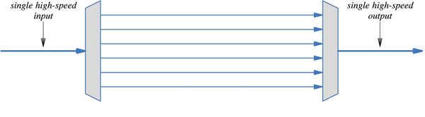
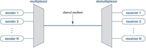
- Multiplexing
- Combining multiple streams for transmission over a single channel.
- Signals must be demultiplexed at the receiver.
- Target channel is usually a physical connection, but might be
virtual, such a s TCP connection.
- Types of multiplexing
- Frequency Division Multiplexing (FDM). Each
signal uses its own frequency.
- Wavelength Division Multiplexing (WDM). This is just FDM when applied
to light signals.
- Time Division Multiplexing (TDM). Taking turns.
- Code Division Multiplexing (CDM). Magic. Signals are combined and
separated using mathmatical operations.
- Frequency Division Multiplexing (FDM).
- Method used for broadcast radio stations or TV channels.
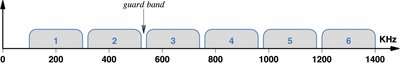
- Each signal is assigned a range of frequencies called a “channel.”
- Each signal is then modulated to a carrier frequency in the center of
its channel.
- These are all sent on the same line; the line contains the sum of
the signals.
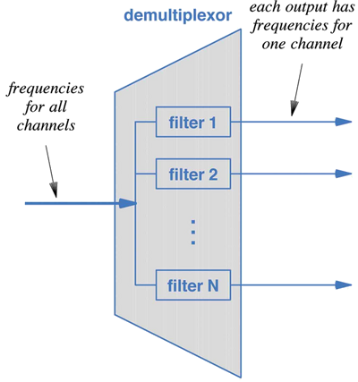
- The demultiplexor is a collection of filters.
- A filter is a specialized circuit which attenuates frequecies outside
the channel.
- Channels are separated by a “guard band” to avoid intra-channel
interference.
- Wave Division Multiplexing (WDM).
- Same using light.
- Separated and combined with prisms.
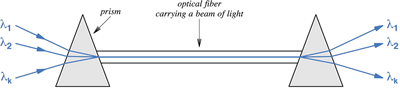
- Channels frequencies are sometimes called “colors.”
- Time Division Multiplexing (TDM)
- Taking turns.
- Synchronous TDM. Each sender is given a turn in rotation.
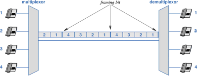
- The data for a channel is broken into peices which are sent in turn.
- Synchronization
- A known bit pattern is sent between rounds to maintain recevier
synchronization.
- Telephone systems use alternating 1 and 0.
- This stream of bits forms a “framing channel.”
- Statistical TDM
- Sychnronous TDM gives each sender a slot, even when it has nothing
to send.
- Statistical TDM just skips those.
- But needs to add a identifier for each frame, since the recevier
can no longer count on strict rotation.
- Code Division Multiplexing (CDM)
- Used in cell phones.
- Bit sequences are represented as vectors,
where sign of each component gives the binary value.
- Data from senders is combined mathematically, combination is sent,
receiver separates them again.
- Stations are assigned special identifiers (“chip sequences.”),
whose vector representations are orthognal (perpendicular).
- Data blocks are combined with their receivers id using the vector
cross product.
- These cross products are summed, and the resulting bit sequence sent.
- The receiver can recover the message by taking the dot product of
the received message and its own id.
- Example from text. Two-bit identifiers.
- ID numbers, 10 and 11. Vector forms, (1,−1) and (1,1).
- They are orthogonal:
(1,−1)⋅(1,1)=1⋅1+−1⋅1=0
- Data sent to each address, 1010 and 0110, respectively. Vector forms
(1,−1,1,−1) and (−1,1,1,−1)
- Compute the cross product of each destination and its message:
(1,−1)×(1,−1,1,−1)=
((1⋅1,−1⋅1),(1⋅−1,−1⋅−1),(1⋅1,−1⋅1),(1⋅−1,−1⋅−1))=
((1,−1),(−1,1),(1,−1),(−1,1))
(1,1)×(−1,1,1,−1)=
((1⋅−1,1⋅−1),(1⋅1,1⋅1),(1⋅1,1⋅1),(1⋅−1,1⋅−1))=
((−1,−1),(1,1),(1,1),(−1,−1))
- Take the sum of these numbers:
| 1 | −1 | −1 | 1 | 1 | −1 | −1 | 1 |
| + | −1 | −1 | 1 | 1 | 1 | 1 | −1 | −1 |
| 0 | −2 | 0 | 2 | 2 | 0 | −2 | 0 |
- Author doesn't say how this value transmitted. Presumably a
signal with an approriate number of levels.
- Each receiver turns it back into a vector and takes the cross product
with its id
(1,−1)⋅((0,−2),(0,2),(2,0),(−2,0))=
((1⋅0+−1⋅−2),(1⋅0+−1⋅2),(1⋅2+−1⋅0)(1⋅−2+−1⋅0))=
(2,−2,2,−2)
- Result is interpreted as 1010, the original message. Other receiver
will be able to extract its message by the same procedure.
- Avoids delays caused by TDM in large networks.
- Inverse Multiplexing
- Sometimes, only low-bandwidth channels are available.
- But, if you afford to use several: